Some Cool Title
The central processor of the control unit in this High Pot system is an ARM-STM32F205.


PCB design and programming of the control system for the high pot system 3.5 kV version 3.0 (condom test device)

In this project, the PCB design and the schematic of the electronic board of the control system of the 3.5 kV high-voltage part for the sanitary condom test device were designed. The programming of this PCB was also carried out in the C/C++ language in the Keil µVision software programming environment. In condom manufacturing factories, it is necessary to test condoms for the absence of holes after initial production. This test is carried out with an electronic testing device or ET. The basis of this device is to create a high-voltage circuit. If the condom has a hole, a short circuit occurs in the circuit and the device rejects the condom.
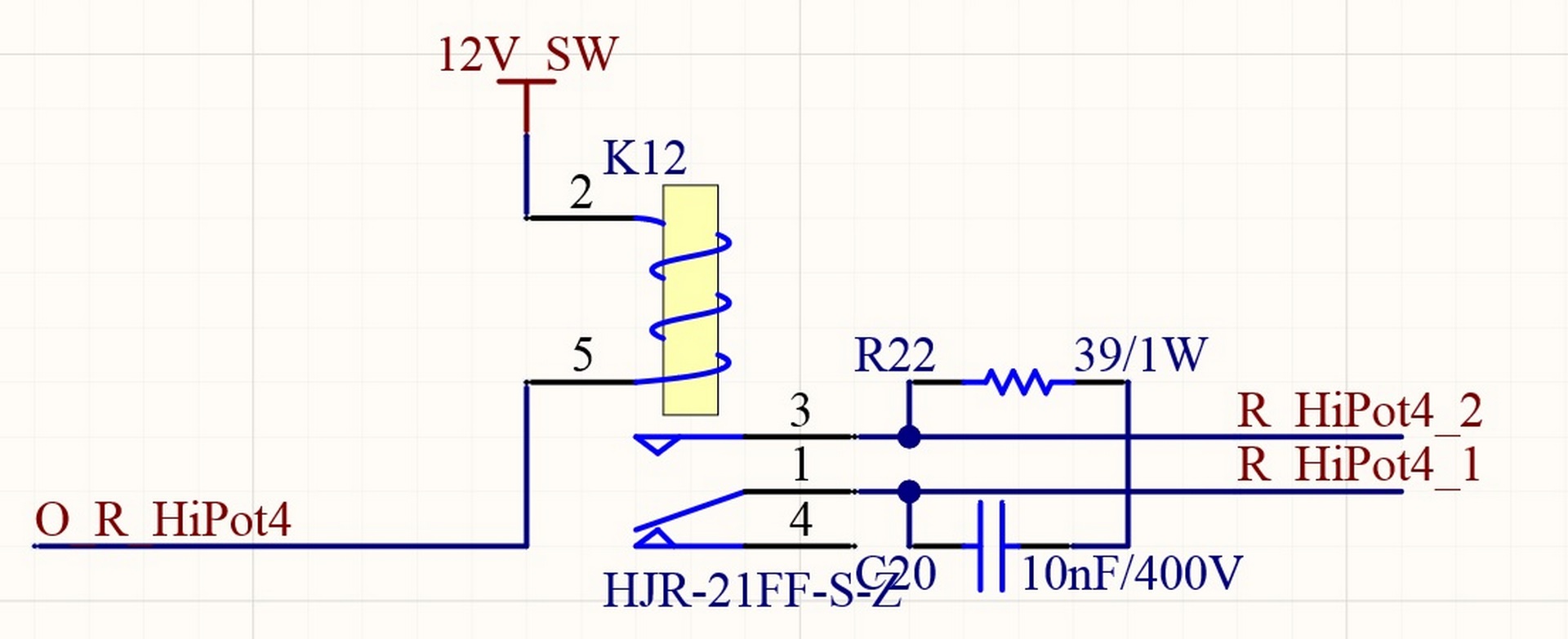
This control system consists of two main parts. The first part is the microcontroller unit and the second part is the relay board. This control system was designed and built to start and control the 3.5 kV high voltage parts of the condom tester.
This control system is able to detect holes on condoms in three areas:
1-Holes in the first area (the hole is in the upper third of the condom)
2-Holes in the second area (the hole is in the middle third of the condom)
3-Holes in the third area (the hole is in the bottom third of the condom)
In version 3 of the high pot systems, it was decided to build a separate high pot system for each area on the mandrel. As we carry out high voltage tests in two stages in the ET device and three areas with different voltages are tested in each stage, 6 high pot packages were produced in this project.
In the figures below, various parts of the schematic and PCB related to this project are shown.


